DC (direct current) track circuits are the simplest, least costly, and most reliable type of track circuit and are therefore the natural first choice for non-electrified railways, typically applied in branch lines between stations or in the main lines of crossing yards. However, the geographical limits of each section must be defined by insulated rail joints installed at the ends of each rail section.
The basic form of a DC track circuit follows the fundamental signaling concept of “fail-safe” procedures. Power is applied to the rails at one end of the section and is transmitted via the rails to a vital DC track relay at the other end, as shown in the figure below.
The DC power, obtained from a main transformer/rectifier, is fed through a feed resistor to the rails. The resistor is necessary to limit the current drawn from the feed unit when the track circuit is shunted by a train and to allow the track circuit's sensitivity to be adjusted. The performance of a DC track circuit is determined by the minimum ballast resistance of the tracks and the section length, with a maximum range of up to 1,200 meters.
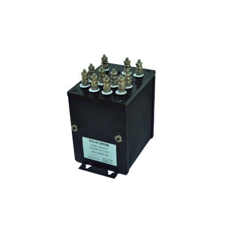
DC track circuits are designed and supplied complete, including relay, transformer, rectifier, resistors, arresters, and accessories such as terminal boards and connectors. Interconnection cables, cross bonds, rail bonds, and insulated rail joints are not included.